Data Collection & Telemetry
Overview
Update Hardware
Module and SIM Update Guides
Module Identification
Module Swap Wizard
SIM Swap Wizard
AT&T / T-Mobile Configuration Guide
Verizon Configuration Guide
Worldwide H1 SIM Configuration Guide
SIM Replacement Instructions
Wi-Fi Configuration Guide
Firmware Update
Troubleshoot
ZL6 Troubleshooting Guide
ATMOS 41W Troubleshooting Guide
EM60G Troubleshooting Guide
EM50 Series Troubleshooting Guide
Communication Test
List Cellular Carriers
Test Button & Status Lights
Fix: Retroactively Enable LTE-M Bands for 4G in Europe
Sensor Current Draw Check - ZSC
App Location Permissions on iOS and Android
Coverage
Accessories
ZENTRA Cloud 1.0
Quick Start
Organizations
Account
Edit Account Profile
Update Account Password
Lost Password/Password Reset
Set Measurement Unit Preferences
Users
Devices
Device Inventory
Edit Device
Re-provision ZL6 to European Server
Add Device
Remove Device
Time-zone and Location Override
Calibrations
Downloads
Dashboard
Enable Chart Status
Create Custom Charts
Color Picklist
Add Traces to Chart
Chart Stats
Print Charts
Set a Target Range
Lock Chart Axes
Chart Date Range Picker [NEW]
Download Chart Data
Notifications
Models
Daily Light Integral [1.0]
Ground Water Elevation [1.0]
Ground Water Depth [1.0]
Plant Available Water [1.0]
Daily Light Photoperiod [1.0]
Chill Hours [1.0]
Growing Degree Days [1.0]
Create a Model [1.0]
Evapotranspiration [1.0]
Subscriptions
Error Codes
Applications
FAQ
ZENTRA Field
ZENTRA Cloud 2.0
Frequently Asked Questions
Getting Started
User Account
Setup
Loggers
Add Data Logger
Configure Data Logger
Map of Data Loggers
Data Logger Charts
Data Logger Download
Logs
Archive
Handhelds
Dashboards
Explorer
Data
Workspaces (Projects)
Alerts
Environment Models
Chill Hours [2.0]
Daily Light Integral [2.0]
Daily Light Photoperiod [2.0]
Evapotranspiration [2.0]
Groundwater Elevation [2.0]
Groundwater Depth [2.0]
Growing Degree Days [2.0]
Heat Index [2.0]
Heat Stress Wet Bulb Globe Temperature WBGT [2.0]
Leaf Wetness Amount of Water [2.0]
Plant Available Water [2.0]
Utah Chill Model [2.0]
Wind Chill [2.0]
Subscriptions
Feedback
API
v3.0/4.0
US Server API
EU Server API
TAHMO Server API
Push API
R Package
API Troubleshoot
AgWeatherNet & DAS
Manage API Keys
v5.0
Metadata
Release Notes
Accessibility
Security
Uptime & Incidents
Legal
Table of Contents
- All Categories
-
- EM50G
EM50G
How to troubleshoot an EM50G data logger.
This article details how to troubleshoot an EM50G data logger.
Download a pdf of this article here.
Visual inspection
- Please make sure all sensors are plugged in securely and fully inserted into the port.
- Inspect sensor cables for damage, cuts, abrasions etc.
- Ensure all 5 batteries are oriented in the correct position. | - | + | - | + | - |
- On the computer board, is there any corrosion or rust visible?
Test button
On the logger, press the reset button for 2 seconds. Wait 10 seconds. Then press the test button for 2 seconds. Wait 30 seconds.
Pressing the Test button initiates the self-test sequence. For EM50G loggers, the self-test can take about 30s to complete. Both the green and red lights blink together slowly while the logger performs tests.
The following actions are part of the self-test sequence:
- Reboots the EM50G. This ensures internal software restarts and is operating in an expected way. Both status lights stay lit during the reboot. This reboot will not erase data or reset settings.
- Perform basic functionality testing on internal systems and evaluates the amount of charge in the battery. Both the green and red lights blink together slowly while the logger performs tests.
- Autodetects connected digital sensors.
- Establish an internet connection over the cellular network and attempts to communicate with the ZENTRA Cloud servers.
After completing the self-tests, the EM50G will indicate success or failure by lighting either the red or green status light.
- A solid green light (for approximately 20s) indicates that internal tests passed and that there was successful communication over the cellular network.
- A solid red light indicates an error in the logger, which may include:
- Corrupt logger firmware
- Low batteries
- Unsuccessful cellular communication
Other possible status states indicated by the green light labeled OK and the red light labeled ERROR are:
- The green light gives a short, single blink every 5 seconds to indicate the logger is configured to log sensor data.
- The green light blinks slowly (1 second on, then 1 second off), to indicate the logger is communicating to a computer or using the cellular module.
- The green and red lights blink together after pressing the test button, pulling the battery tab, or installing batteries.
- The lights remain off if the logger measurement interval is set to "Off (not logging)".
- The red light stays on solid. Contact METER for support.
ECH2O Utility
To connect to the logger you need a Decagon USB to Stereo adapter cable. If a connection cannot be made, try a different cable. If you do not have the proper cable contact METER to request a new cable.
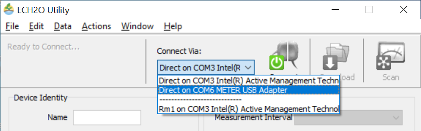
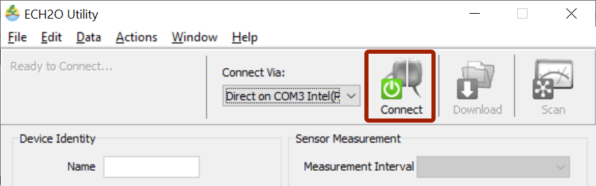
- Open ECH2O Utility
- Under connect Via you should see an option for “METER“.
- Click Connect.
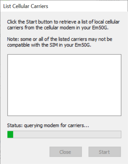
List carriers
- Click Actions
- List Cellular Carriers
- Click Start to begin the test
When the test is complete a list of cellular carriers in the area will be shown. If the test fails move a few feet and try again. After the test successfully lists a cellular carrier, proceed to the next step.
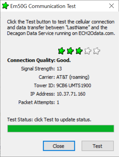
Communications test
- Click Actions
- Communication Test
- Click Test to begin the cellular communication.
When the test is complete the signal strength, carrier, packet attempts and status of the test will be displayed. If the test fails or has low signal, move a few feet and try again.
For the best signal the antenna should be unobstructed by structures or vegetation. If required an extension cable can be used to elevate the antenna.
Sensor connection issues
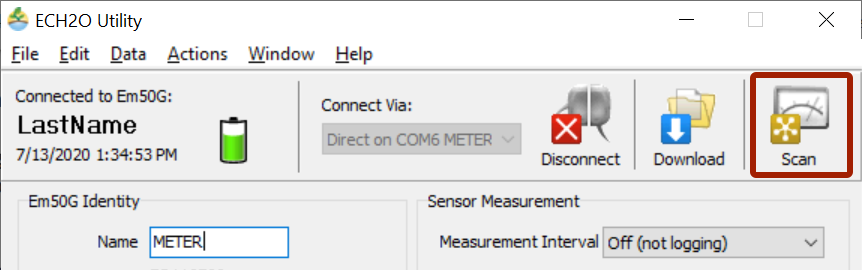
To check sensor communication to the logger when there is no visible damage open ECH2O Utility.
- Press the SCAN button
What to try if the scan result is "invalid input" or an unreasonable measurement value:
- Manipulate the cable at the stereo end while scanning and observe the result.
- Unplug and plug the sensor then scan again.
- Clean the connection. Use isopropyl alcohol if available or water and a clean cloth.
- Plug the sensor into a different port and repeat the scan.
- Try a different sensor in the port that was giving errors.
If the sensor responds when moving it to a different port the device will need to be sent in for repair.
If the sensor responds when the cable is manipulated the cable or connector sensor is bad and should come in for repair/replacement.
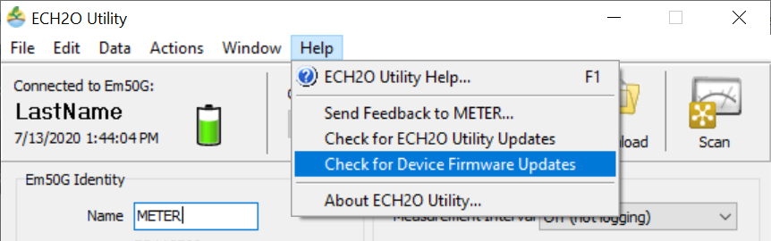
Device firmware
Device firmware should be kept up to date. To check for updates,
- Click Help
- Check for Device Firmware Updates
Drivers and software
If you are running a Windows XP operating system contact METER at support.environment@metergroup.com
How did we do?